


This article describes overview of 5G NR MAC layer. It covers 5G NR MAC functions, 5G NR MAC architecture, 5G NR MAC channel mapping, 5G NR MAC procedures and format of 5G NR MAC header and subheaders.
Table of Contents
- Introduction
- MAC Layer
- Function of MAC Layer
- Services Provided by MAC
- MAC PDU for RACH
- MAC PDU for RAR
- MAC PDU for MSGB
- 5G NR MAC PDU vs 4G LTE MAC PDU
- 5G NR MAC Sub-header.
Introduction
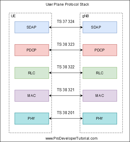
5G NR Protocol stack is divided into 2 planes: User Plane and Control Plane.
User Plane is used to transfer user data and control plane is used to transfer system control signalling transmission.
5G NR User Plane Protocol Stack below picture
5G NR Control Plane Protocol Stack below picture

MAC Layer
MAC stands for Medium Access Control
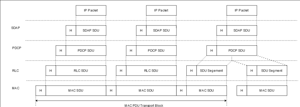
An RLC PDU(Protocol Data Unit) consist of RLC header and a RLC payload.
At MAC layer, an RLC PDU is called as MAC SDU (Service Data Unit). Then MAC adds a Subheader to this and will become MAC sub PDU.
Multiple MAC SDU and CEs can be part of single MAC PDU.
Functions of MAC Layer
1. Mapping between logical and transport channel.
2. Combine MAC SDU from different logical channel into one transport block and deliver to lower layer.
3. Decompose MAC SDU received from lower layer and deliver to different channels.
4. HARQ
5. LCP: Logical channel priority
6. BSR: Buffer Status Report
7. RACH: Random access
8. Uplink timing maintenance
9. PHR: Power headroom report
10. DRX.
Services provided by MAC
Services provided by MAC layer to upper layer:
1. data transfer
Services expected by MAC layer from lower PHY layer:
1. Data transmission.
2. HARQ feedback indication.
3. Scheduling request signaling.
4. Measurement.
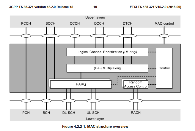
Channel Mapping at MAC Layer
MAC layer Downlink channel mapping

MAC Layer Uplink Channel Mapping

CCCH: Common Control Channel: When UE and gNB(network) have not established an RRC Connection, this channel is used to transmit control information.
DCCH: Dedicated Control Channel: When UE and gNB(network) have established an RRC Connection, this channel is used to transmit control information.
DTCH: Dedicated Traffic Channel: User to transmit UE data in both uplink and downlink.
Below shows complete diagram of MAC Entity
5G NR MAC PDU for RACH
After sending Msg1, UE will monitor PDCCH window and then PDCCH will indicate the location of PDSCH and PDSCH will contain RAR.
Msg2 is a RAR message.
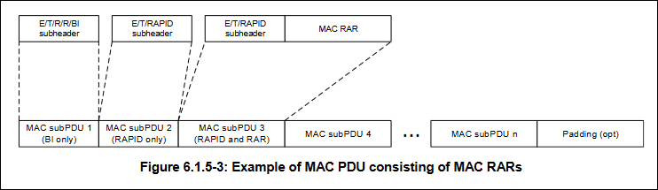
MAC PDU for Random Access Response (RAR)
4 Step RACH process for MAC PDU, it consists of one or more MAC subPDUs and optionally padding. Each MAC subPDU consists one of the
following:
– a MAC subheader with Backoff Indicator only;
– a MAC subheader with RAPID only (i.e. acknowledgment for SI request);
– a MAC subheader with RAPID and MAC RAR
It means MAC subPDU or only one BI subhearder, or only one RAPID subheader, or both RAPID subheader and RAR.
BI subheader may or may not be present, as it is used to indicate the backoff time after Msg2 reception fails.
Every MAC PDU follows below rules:
1. A MSC subPDU with BI is placed at the beginning of the MAC PDU if included.
2. Padding is placed at the end of the MAC PDU if present.
3. MAC subPDU with RAPID only and MAC subPDU(s) with RAPID and MAC RAR can be placed anywhere between MAC subPDU with BI and padding.

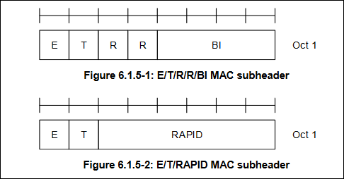
Below image indicates BI subheader and RAPID subheader
A MAC subheader with Backoff Indicator consists of five header fields E/T/R/R/BI
A MAC subheader with RAPID consists of three header fields E/T/RAPID as described in Figure 6.1.5-2.

E (Extension): Used to indicate whether this MAC subPDU is the last one in a string.
– set to “1” to indicate at least another MAC subPDU follows.
– set to “0” to indicate that this MAC subPDUis the last MAC subPDU.
5G NR MAC PDU for RACH
After sending Msg1, UE will monitor PDCCH window and then PDCCH will indicate the location of PDSCH and PDSCH will contain RAR.
Msg2 is a RAR message.
We will discuss MAC PDU for 2 step RACH in this chapter only.
MAC PDU for Random Access Response [4 step RACH]
A MAC PDU consists of one or more MAC subPDUs and optionally padding. Each MAC subPDU consists one of the following:
- – A MAC subheader with Backoff Indicator only;
- – A MAC subheader with RAPID only (i.e. acknowledgment for SI request);
- – A MAC subheader with RAPID and MAC RAR
It means MAC subPDU or only one BI subhearder, or only one RAPID subheader, or both RAPID subheader and RAR.
BI subheader may or may not be present, as it is used to indicate the backoff time after Msg2 reception fails.
Every MAC PDU follows below rules:
1. A MSC subPDU with BI is placed at the beginning of the MAC PDU if included.
2. Padding is placed at the end of the MAC PDU if present.
3. MAC subPDU with RAPID only and MAC subPDU(s) with RAPID and MAC RAR can be placed anywhere between MAC subPDU with BI and padding.
Below image indicates BI subheader and RAPID subheader
A MAC subheader with Backoff Indicator consists of five header fields E/T/R/R/BI
A MAC subheader with RAPID consists of three header fields E/T/RAPID as described in Figure 6.1.5-2.
E (Extension): Used to indicate whether this MAC subPDU is the last one in a string.
– set to “1” to indicate at least another MAC subPDU follows.
– set to “0” to indicate that this MAC subPDUis the last MAC subPDU;
T (Type): Used to indicate whether the MAC subheader is RAPID subheader or BI subheader.
– set to “0” to indicate the presence of a BI field in the subheader (BI).
– set to “1” to indicate the presence of a RAPID field in the subheader (RAPID).
R: reserved bit, set to “0”.
BI: Backoff Indicator. The size of the BI field is 4 bits.
RAPID: The Random Access Preamble IDentifier. The size of the RAPID field is 6 bits.
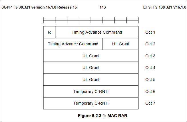
R: reserved bit, set to “0”.
Timing Advance Command: This is the timing advance instruction, which tells the UE the timing advance information, a total of 12 bits.
UL Grant: Uplink scheduling indication, indicating the PUSCH information occupied by subsequent Msg3 transmissions, a total of 27 bits.
Temporary C-RNTI: The temporary C-RNTI allocated to the UE by the network. The UE that is not in the CONNECTED state does not have a C-RNTI. Therefore, the network needs to allocate a temporary C-RNTI to the UE. This temporary subsequent random access is successful. It will be upgraded to a real C-RNTI, a total of 16 bits.
UL grant: RAR UL grant is used to schedule the transmission of Msg3 PUSCH, including the following:
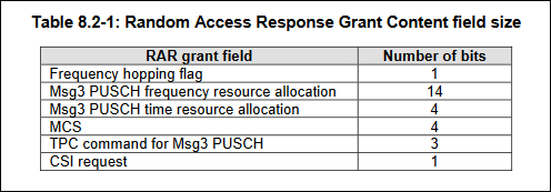
- Frequency hopping flag: If 1 then UE has to perform frequency hopping, else 0.
- Msg3 PUSCH frequency resource allocation
- Msg3 PUSCH time resource allocation
- MCS: It indicates the modulation and coding strategy (refer to 38214 for details).
- TPC command for Msg3 PUSCH: It indicates the transmission power of PUSCH. For details, please refer to [TS 38.213]
- CSI request. It is reserved.
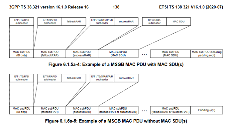
MAC PDU for MSGB [2 step RACH]
A MAC PDU consists of one or more MAC subPDUs and optionally padding. Each MAC subPDU consists one of the following:
- – A MAC subheader with Backoff Indicator only;
- – A MAC subheader and fallbackRAR;
- – A MAC subheader and successRAR;
- – A MAC subheader and MAC SDU for CCCH or DCCH;
- – A MAC subheader and padding
5G NR MAC Sub Headers, MAC PDU and MAC Control Elements

5G NR MAC PDU vs LTE MAC PDU
From the image below we can infer below points:
1. A MAC PDU in LTE has a single header that has all the information for decoding the entire PDU.
2. A MAC PDU in 5G NR has one or more sub headers and each sub header providing information to decode corresponding MAC PDU.
This helps to reduce the latency in 5G NR.
MAC sends/receives Control Elements with its own sub header.
Note:
1. In LTE RLC layer does the concatenation of RLC PDU.
2. In 5G NR RLC does not do concatenation. An RLC data PDU contain only one RLC SDU. Multiplexing/demultiplexing of RLC PDU will be done at MAC

MAC PDU 5G NR
There are different types of MAC PDU but has general structure:
- Downlink MAC PDU
- Uplink MAC PDU
- Sidelink Channel PDU
- Random Access Procedure PDU
A MAC PDU consists of one or more MAC subPDU. Each MAC subPDU consists of one of the following:
- A MAC subheader only (including padding);
- A MAC subheader and a MAC SDU;
- A MAC subheader and a MAC CE;
- A MAC subheader and padding.
Each MAC subheader corresponds to either a MAC SDU, a MAC CE, or padding.
Below shows an example of DL and UL MAC PDU

1. For DL PDU, that required subPDU assembly CEs take precedence over SDU, SDU takes precedence over padding.
2. For UL PDU, that required subPDU assembly SDUs take precedence over CEs, CEs takes precedence over padding.
A MAC PDU will have one or more MAC sub PDU.
A MAC subPDU always start with a subheader. A sub-header is followed by a MAC SDU, a MAC CE or padding.
If a MAC subPDU doesnt fill a TB, a MAC subPDU with padding is included.
All MAC SDU, CE and sub-header are aligned in multiple of 8 bits.
5G NR MAC subheader
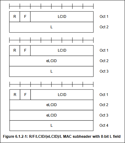
R : Reserved: It is set to 0 as it can be used for further use.
F : Format: It indicated the size of Length field L. If F = 0 L is 8 else L is 16 bits.
L: Length: It indicates the length in bytes of either a MAC SDU or variable sized CE.
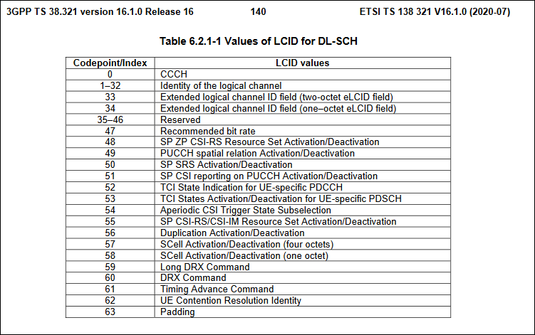
LCID: Logical Channel ID: It is a 6-bit field that identifies the logical channel carried in a MAC subPDU a specific CE or padding.
eLCID: Extended Logical Channel ID: This extends the range of LCID field.
LCID field in MAC Subheader based on 38.321