


Table of Contents
- Introduction
- Service by RLC Layer
- Function by RLC Layer
- RLC Layer Entity
- RLC Procedures
- 5G NR RLC vs 4G RLC
- RLC Entity Establishment
- RLC Entity Release
- RLC State Variables, Constant and Timers
- 5G NR RLC TM PDU
- 5G NR RLC UM PDU
- 5G NR RLC AM PDU
- 5G NR RLC ARQ Procedure
Introduction
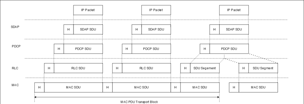
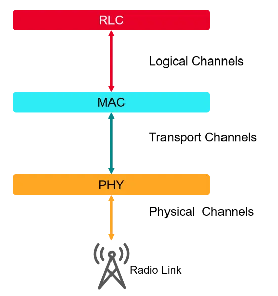
The Radio Link Control (RLC) sublayer of 5G NR protocol stack interfaces to PDCP sublayer from above and MAC sublayer from below. It interfaces to PDCP via RLC channels and to MAC via logical channels. There’s a one-to-one mapping: RLC SDUs belonging to an RLC channel are mapped to a single logical channel.
An RLC entity in a 5G UE has its peer RLC entity in the gNB, or other UEs in the case of NR sidelink communication. An RLC entity can be configured in one of three transmission modes: Transparent Mode (TM), Unacknowledged Mode (UM) and Acknowledged Mode (AM). Each mode supports a set of functions. Mode is configured by RRC and depends on the higher layer service requirements.

RLC layer is located between PDCP (or RRC layer) and MAC Layer. It communicates with the PDCP layer (or RRC layer) through the RLC channel, and communicates with the MAC layer through logical channels. Data received by RLC layer from PDCP layer is called as RLC SDU. Data sent by RLC layer to MAC layer is called as RLC PDU. RLC PDU can be either RLC data PDU or RLC control PDU.
Services Provided to upper layers from RLC layer:
- TM data transfer
- UM data transfer
- AM data transfer, including indication of successful delivery of upper layers PDUs
Services Expected from lower layers to RLC layer:
- Data transfer
- Notification of a transmission opportunity, together with the total size of the RLC PDU(s) to be transmitted in the transmission opportunity.
Functions of RLC layer
- Transfer of upper layer PDUs
- Error correction through ARQ (only for AM data transfer)
- Segmentation and reassembly of RLC SDUs (only for UM and AM data transfer)
- Re-segmentation of RLC SDU segments (only for AM data transfer)
- Duplicate detection (only for AM data transfer)
- RLC SDU discard (only for UM and AM data transfer)
- RLC re-establishment
- Protocol error detection (only for AM data transfer).
5G NR operates in 3 different modes:
- TM: Transparent Mode: There will be No RLC Header, No Segmentation/Reassembly, No feedback
- UM: Unacknowledge Mode: RLC Header, Buffering at both Tx and Rx, Segmentation/Reassembly, No feedback
- AM: Acknowledge Mode: RLC Header, Buffering at both Tx and Rx, Segmentation/Reassembly, Feedback
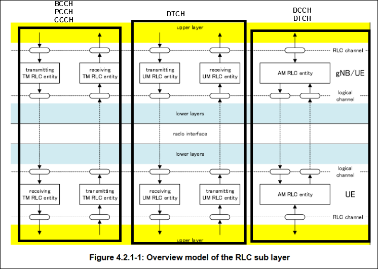
From the above image we can see below points:
- BCCH, PCCH, CCCH use RLC TM
- DCCH use RLC AM
- DTCH use RLC UM or AM
- SRB0 bearer, paging and system information broadcast use TM transmission mode
- Other SRB bearers use AM transmission mode
- DRB bearer can use AM or UM mode
Entities:
The TM transmission mode includes two entities: a sending entity and a receiving entity.The UM transmission mode includes two entities: a sending entity and a receiving entity;. transmission mode contains only one entity for both sending and receiving to facilitate ARQ processing.
RLC Procedures
- TM data transfer Procedure
- UM data transfer Procedure
- AM data transfer Procedure
- ARQ procedure
How 5G NR RLC is different than 4G LTE RLC?
5G NR RLC cannot do Concatenation. Concatenation is when a multiple RLC SDU can be combined into a single RLC PDU. Segmentation is when a single RLC SDU is segmented into multiple RLC PDU. LTE RLC can do both Concatenation and Segmentation. Where as 5G NR RLC cannot do Concatenation and but can do Segmentation.
RLC entity establishment procedure
When any upper layer request an RLC entity establishment, the UE will
- Establish a RLC entity.
- Set the state variables of the RLC entity to initial values.
- Then perform Data transfer procedures
RLC entity re-establishment
When upper layers request an RLC entity re-establishment, the UE shall.
- Discard all RLC SDUs, RLC SDU segments, and RLC PDUs, if any.
- Stop and reset all timers;
- Reset all state variables to their initial values.
RLC entity release
When upper layers request an RLC entity release, the UE shall:
- Discard all RLC SDUs, RLC SDU segments, and RLC PDUs, if any
- Release the RLC entity.
RLC Parameters
SN = Sequence Number. All state variables related to AM data transfer can take values from 0 to 4095 for 12 bit SN or from 0 to 262143 for 18 bit SN.All state variables related to UM data transfer can take values from 0 to 63 for 6 bit SN or from 0 to 4095 for 12 bit SN.
Below are the state variables of transmitting side of each AM RLC entity:
- TX_Next_Ack: Acknowledgement state variable . It is a state variable that holds the value of SN of the next RLC SDU for which a positive ack is to be received in sequence
- TX_Next – Send state variable . This state variable holds the value of the SN to be assigned for the next newly generated AMD PDU.
- POLL_SN – Poll send state variable . This state variable holds the value of the highest SN of the AMD PDU among the AMD PDUs submitted to lower layer when POLL_SN is set according to sub clause 5.3.3.2. It is initially set to 0.
Below are the counters of transmitting side of each AM RLC entity:
- PDU_WITHOUT_POLL – Counter . This counter is initially set to 0. It counts the number of AMD PDUs sent since the most recent poll bit was transmitted.
- BYTE_WITHOUT_POLL – Counter . This counter is initially set to 0. It counts the number of data bytes sent since the most recent poll bit was transmitted.
- RETX_COUNT – Counter . This counter counts the number of retransmissions of an RLC SDU or RLC SDU segment
Below are the state variables of receiving side of each AM RLC entity:
- RX_Next – Receive state variable . This state variable holds the value of the SN following the last in-sequence completely received RLC SDU
- RX_Next_Status_Trigger – t-Reassembly state variable . This state variable holds the value of the SN following the SN of the RLC SDU which triggered t-Reassembly.
- RX_Highest_Status – Maximum STATUS transmit state variable. This state variable holds the highest possible value of the SN which can be indicated by “ACK_SN” when a STATUS PDU needs to be constructed. It is initially set to 0.
- RX_Next_Highest – Highest received state variable. This state variable holds the value of the SN following the SN of the RLC SDU with the highest SN among received RLC SDUs. It is initially set to 0.
Below are the state variables of transmitting UM RLC entity:
TX_Next – UM send state variable. This state variable holds the value of the SN to be assigned for the next newly generated UMD PDU with segment.
Below are the state variables of receiving UM RLC entity :
- RX_Next_Reassembly – UM receive state variable . This state variable holds the value of the earliest SN that is still considered for reassembly. It is initially set to 0.
- RX_Timer_Trigger – UM t-Reassembly state variable . This state variable holds the value of the SN following the SN which triggered t-Reassembly.
- RX_Next_Highest– UM receive state variable . This state variable holds the value of the SN following the SN of the UMD PDU with the highest SN among received UMD PDUs.
Constants
- AM_Window_Size: Used by transmitting and receiving of AM entity. AM_Window_Size = 2048 when a 12 bit SN is used, AM_Window_Size = 131072 when an 18 bit SN is used.
- UM_Window_Size: This constant is used by the receiving UM RLC entity to define SNs of those UMD SDUs that can be received without causing an advancement of the receiving window. UM_Window_Size = 32 when a 6 bit SN is configured, UM_Window_Size = 2048 when a 12 bit SN is configured.
Timers
- t-PollRetransmit: This timer is used by transmitting AM RLC in order to retransmit a poll.
- t-Reassembly: This timer is used by receiving AM and UM RLC in order to detect loss of RLC PDUs at lower layer.
- t-StatusProhibit: This timer is used by the receiving side of an AM RLC entity in order to prohibit transmission of a STATUS PDU
Configurable parameters by RRC layer
- maxRetxThreshold: This counter is used to limit the number of retransmissions of an RLC SDU
- pollPDU: It is used to trigger a poll for every pollPDU.
- pollByte: It to trigger a poll for every pollByte bytes.
5G NR RLC TM PDU and data transfer procedure
In TM mode, RLC does not perform any operations on the SDU and it is transmitted transparently.It will only buffer data on Tx side. No RLC header, No reordering, No segmentation, no reassembly is done.The PDU that is transmitted is called as TMD PDU.
TM Data Transfer Procedure
A TM entity will perform below transmit operations.
- Submit an RLC SDU without any modification to lower layers
- A TM entity will perform below receive operations.
- Deliver the TMD PDU without any modification to upper layer.
Note: We know that RLC layer supports 3 modes: TM/UM/AM. Now the question arises which mode to be used ? TM/UM is used for real-time services. Because, real-time services goal is to minimize the delay and where a small amount of data loss is acceptable. AM is used for non-real-time services. Here bit of delay is tolerable but higher transmission quality is required.
5G NR RLC UM PDU
UM stands for “Unacknowledged Mode”.In UM mode, RLC adds protocol header to RLC SDU and if required SDU can be segmented.The transmitting entity performs the below operation:
- Buffering of the data and generate RLC header.
- Segmentation and modify RLC header
- Add RLC header.
The receiving entity performs the below operation:
- Buffering of the data.
- Reordering
- Remove RLC header.
- Reassembly.
UM Data Transfer Procedure
State variables for Transmitting UM entity
- TX_Next: This variable indicates the SN (Sequence Number) of the next UMD PDU that contains the RLC SDU segment to be constructed. It will be updated every time the last segment is reached.
- State variables for Receiving UM entity
- RX_Next_Reassembly: This variable points to the earliest SN among all packets to be reassembled.
- RX_Timer_Trigger: This variable points to the SN+1 of the packet that triggered the timer t-Reassembly.
- RX_Next_Highest: This variable points to the largest SN+1 among all UMD PDU received. It is the upper boundary of the receiving window
- UM_Window_Size: The constant is the size of the reassembly window, 32 for 6 bit SN, and 2048 for 12 bit SN;
- RX_Next_Highest – UM_Window_Size: The upper boundary – the window size will give the lower boundary for reassembly.
- RLC UM Timer:
- t-Reassembly: This timer is used at the receiving end to detect whether there is a packet loss. It means, if a packet is not received, then receiving entity cannot wait indefinitely.
UM transmit operations
If the UMD PDU contains a segment of a RLC SDU then it will set the SN of the UMD PDU to TX_Next. i.e TX_Next = SN.If the UMD PDU contains a segment that maps to the last byte of an RLC SDU, then increment TX_Next by one.
UM Receive operations
There are 3 different cases on how to handle UM Receive Operations as below:
- Actions when an UMD PDU is received from lower layer
- Actions when an UMD PDU is placed in the reception buffer
- Actions when t-Reassembly expires
1. Actions when an UMD PDU is received from lower layer
If the UMD PDU does not have an SN, it means that the UMD PDU is a complete RLC SDU, and the RLC header is removed and sent to the PDCP immediately.
If (RX_Next_Highest – UM_Window_Size) <= SN < RX_Next_Reassembly, then discard the packet. Because the SN is smaller than RX_Next_Reassembly, WKT RX_Next_Reassembly is the smallest SN of the packets to be reassembled.
Else, put the UMD PDU to reception buffer.There is no need to submit the packets in order. The reassemble window can be moved depending on the RX_Next_Highest variable
2. Actions when an UMD PDU is placed in the reception buffer
Consider an UMD PDU with SN = x and is placed in reception buffer, then:
- If all the segments are received, then it will be sent to PDCP layer after header removal. Then update RX_Next_Highest to SN + 1. Example: If the largest SN received before = 5, then RX_Next_Highest=6, if SN=8 is received, update RX_Next_Highest=9. But the packets between SN=5 and SN =8, might be lost, UM mode will not guarantee the packet loss.
- If x = RX_Next_Reassembly, then update the RX_Next_Reassembly to the SN of the first SN > current RX_Next_Reassembly that has not been reassembled and delivered to upper layer.
- If x falls outside the reassembly window, then update RX_Next_Highest to x + 1 and discard any UMD PDUs with SN that falls outside of the reassembly window.
The receiving window maintains as follows:
(RX_Next_Highest – UM_Window_Size) <= SN <RX_Next_Highest . It means, the receiving window can be moved on the update of the upper boundary i.e RX_Next_Highest.
t-Reassembly timer start and stop conditions
Start Condition:
If t-Reassembly timer is not running, then start the timer, if any of the conditions are met:
- RX_Next_Highest > RX_Next_Reassembly + 1. It means, for example, if the packet with SN = 8 is received, RX_Next_Highest = 9 is updated, since the previous packet is SN=5, RX_Next_Reassembly=6, the condition is met, start the timer, and update RX_Timer_Trigger=9.
- if RX_Next_Highest = RX_Next_Reassembly + 1 and there is at least one missing byte segment of the RLC SDU associated with SN = RX_Next_Reassembly before the last byte of all received segments of this RLC SDU.
It means, for example, we receive a packet for SN =6 and the segment with SN= 6 is not received completely, update RX_Next_Highest=7, the previous packet is SN=5, RX_Next_Reassembly=6, and the conditions are met , Start the timer, update RX_Timer_Trigger=7.
Stop Condition:
- RX_Timer_Trigger <= RX_Next_Reassembly
- if RX_Timer_Trigger falls outside of the reassembly window and RX_Timer_Trigger is not equal to RX_Next_Highest
- if RX_Next_Highest = RX_Next_Reassembly + 1 and there is no missing byte segment of the RLC SDU associated with SN = RX_Next_Reassembly before the last byte of all received segments of this RLC SDU
Actions when t-Reassembly expires
- Update the RX_Next_Reassembly to the SN of the first SN >= RX_Timer_Trigger that has not been reassembled.
- Discard all segments with SN < updated RX_Next_Reassembly.
5G NR RLC AM PDU
AM stands for “Acknowledge Mode”. In AM mode, RLC adds protocol header to the RLC SDU and if necessary, the RLC SDU can be segmented and then protocol header is updated. AM mode expects ACK/NACK from the other party.
AM supports ARQ transmission. When the size of retransmitted RLC SDU does not match the size indicated by the MAC, the RLC SDDU can be divided or re-segmented.
Retransmission buffer
RLC control.
After RLC PDU has been transmitted, a similar copy will be stored in Retransmission buffer. If the RLC get NACK or does not get any positive response, then the RLC packet from Retransmission buffer will be transmitted again. If RLC gets an ACK, then that packet will be discarded.
AM Data Transfer Procedure
State variables for Transmitting AM entity
- TX_Next_Ack: This variable points to the smallest SN expected to receive ACK. Example, if AMD PDU 1, 2, 3, 4. We receive positive ACK for 1, 2, 3, and then send AMD PDU 5, and receive +ve ACk for SN 5, but did not receive +ve ack for SN 4, then this variable will hold SH = 4.
- TX_Next : This variable points to the SN of the AMD PDU to be constructed next.
- POLL_SN: This variable is the largest SN in all AMD PDUs sent to the MAC layer.
- State variables for Receiving AM entity
- RX_Next : This variable points to the SN+1 that has been correctly received. Example if SN = 1, 2, 3 has been received and instead of SN=4, it receives SN=5, RX_Next will be 4, because it did not receive correctly.
- RX_Next_Status_Trigger : This variable points to SN+1 that triggers t-Reassembly.
- RX_Highest_Status : This variable indicates the highest possible SN that can be indicated by ACK_SN when constructing STATUS PDU.
- RX_Next_Highest : This variable points to the largest SN+1 among all received RLC SDUs.
AM transmit operations
The transmitting side of AM RLC entity will prioritize the transmission as below:
- RLC control PDUs over AMD PDUs
- AMD PDUs containing previously transmitted RLC SDUs or RLC SDU segments
- New AMD PDUs
The sender will maintain a transmitting window according to the state variable “TX_Next_Ack”: TX_Next_Ack <= SN < TX_Next_Ack + AM_Window_Size. AMD PDU falls outside this window will not be transmitted. So it means that TX_Next_Ack is the lower boundary of the sending window.
When AM entity receives an RLC SDDU from upperlayer, then it will assign SN = TX_Next and construct AMD PDU with that SN. Then Increment TX_Next by one. Then an AM RLC entity can receive +ve ack from the peer RLC entity by STATUS PDU and informs the upper layer of successful delivery of the RLC SDU.
Then set TX_Next_Ack equal to the SN of the RLC SDU with the smallest SN, whose SN falls within the range TX_Next_Ack <= SN <= TX_Next and for which a positive acknowledgment has not been received yet.
AM Receive operations
The receiving end will maintain a receiving window according to the state variable RX_Next as follows:
RX_Next <= SN < RX_Next + AM_Window_Size
So any AMD DPU received that is not in the receiving window or a duplicate SN, then it will be discarded.else AMD PDU containing the RLC SDU segment is placed in reception buffer. SN = 0, 1, 2 and 4 have been received correctly. RX_Next = 3 and window size is 4. So the window range will be [3, 7). If we receive SN<3 and SN >=7 they will be discarded.
AMD PDU is placed in the reception buffer
When an AMD PDU with SN = x is placed in the reception buffer. If all the bytes for the RLC SDU with SN = x is received, then reassemble and remove RLC headers and deliver to upper layer.
Update RX_Next_Highest to x+ 1.
Then update RX_Highest_Status and RX_Next accordingly.
Start and stop of t-Reassembly timer
Start condition:
- RX_Next_Highest> RX_Next +1
- RX_Next_Highest = RX_Next + 1 and there is at least one missing byte segment of the SDU associated with SN = RX_Next before the last byte of all received segments of this SDU
Stop condition:
- RX_Next_Status_Trigger = RX_Next.
- RX_Next_Status_Trigger = RX_Next + 1 and there is no missing byte segment of the SDU associated with SN = RX_Next before the last byte of all received segments of this SDU
- RX_Next_Status_Trigger falls outside of the receiving window and RX_Next_Status_Trigger is not equal to RX_Next + AM_Window_Size:
Actions when t-Reassembly expires
When t-Reassembly expires, the receiving side of an AM RLC entity shall
- Update RX_Highest_Status to the SN of the first RLC SDU with SN >= RX_Next_Status_Trigger for which not all bytes have been received;
- Start t-Reassembly timer if below conditions are met: RX_Next_Highest> RX_Highest_Status +1: or RX_Next_Highest = RX_Highest_Status + 1 and SN = RX_Highest_Status RLC SDU has not been collected.
RLC AM PDU
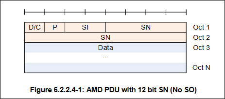
- Data/Control (D/C) field
- Polling bit (P) field
- Segment Offset (SO) field
- Segmentation Info (SI) field
- Sequence Number (SN) field
- Reserved (R) field
- Control PDU Type (CPT) field
MD PDU consists of a Data field and an AMD PDU header. It means all AMD PDU will have a D/C field. An AMD PDU header contains the SO field only when the Data field consists of an RLC SDU segment which is not the first segment, in which case a 16 bit SO is present.
AMD PDU doesnot carry SO. So it means that this PDU is a non segmented PDU or the first segment of Segmented SDU.
AMD PDU carries SO

Status PDU is sued to carry information like ACK sequence number, NACK sequence number

5G NR RLC ARQ Procedure
ARQ: Automatic Repeat Request
In this procedure, RLC re-transmits RLC PDU or RLC PDU segment according to RLC status report. RLC sending entity can request RLC status report as needed. The AM RLC entity provides ACK/NACK to the peer M RLC entity through the STATUS PDU. An AM RLC entity will send STATUS PDU when
- Receive Polling from the peer AM RLC entity.
- Failed to receive AM PDU detected.
Below are the list of Counter and Timer involved in the ARQ process.
Counter
- PDU_WITHOUT_POLL: It indicates the number of newly transmitted AMD PDU before the most recent poll.
- BYTE_WITHOUT_POLL : It indicates the number of bytes of the newly transmitted AMD PDU before the last poll.
- RETX_COUNT: It is the re-transmission counter. It will record the number of re-transmission of each RLC SDU or RLC SDU segment.
- Timer
- t-PollRetransmit: The sender starts after sending polling and stops after receiving STATUS PDU.
- t-StatusProhibit: This timer is started after the receiving side send STATUS PDU.
Retransmission
We know in AM mode, ARQ is supported. ARQ is achieved.
1. Retransmission
2. Polling
3. Status reporting
Retransmission When the receiving side did not receive any packet successfully, it will send NACK to sending entity through STATUS PDU. The Tx side will re-transmit the failed packet (RLC SDU or RLC SDU segment) based on below conditions:
1. if the SN of the corresponding RLC SDU falls within the range TX_Next_Ack <= SN < = the highest SN of the AMD PDU among the AMD PDUs submitted to lower layer. It means, TX_Next_Ack points to the next SN that expects to receive ACK. It means all other packets before TX_Next_Ack have received Ack. “the highest SN” points to the largest SN sent by the Tx side.
2. if the RLC SDU or RLC SDU segment is considered for retransmission for the first time:
–> set the RETX_COUNT associated with the RLC SDU to zero
-> else if it is not the first re-transmission, then increment RETX_COUNT. Then when RETX_COUNT = maxRetxThreshold, RLC will indicate upper layer that the max re-transmission has been reached. When constructing AMD PDU, if the AMD PDU must be inline with MAC layer grant. If it is not, segmentation is necessary.
Polling
AN AM RLC entity can poll its AM RLC peer entity in order to trigger STATUS reporting. For each new transmission (it should not contain already transmitted RLC SDU), then Tx AM RLC entity will PDU_WITHOUT_POLL + 1, BYTE_WITHOUT_POLL + 1 and when the counter reached the threshold and one of the following condition is met, then Tx wil include a poll in AMD PDU.l
- if PDU_WITHOUT_POLL >= pollPDU; or
- if BYTE_WITHOUT_POLL >= pollByte.
To include a poll in AMD PDU, below condition should be met:
- if both the transmission buffer and the retransmission buffer becomes empty or
- if no new RLC SDU can be transmitted after the transmission of the AMD PDU
To include a poll in an AMD PDU, the transmitting side of an AM RLC entity shall:
- set the P field of the AMD PDU to “1”;
- set PDU_WITHOUT_POLL to 0;
- set BYTE_WITHOUT_POLL to 0
- start or restart t-PollRetransmit.
Upon Reception of a STATUS report, stop t-PollRetransmit.
Status reporting
An AM RLC entity sends STATUS PDUs to its peer AM RLC entity in order to provide positive and/or negative acknowledgements of RLC SDUs.
Triggers for STATUS reporting:
- Polling from its peer AM RLC entity
- If the AMD PDU is to be discarded
- The receiving side of an AM RLC entity shall trigger a STATUS report when t-Reassembly expires
When a STATUS PDU has been submitted to lower layer, the receiving side of an AM RLC entity shall start t-StatusProhibit.
When constructing STATUS PDU, the AM RLC entity shall:
1. first construct the a STATUS PDU for the RLC SDUs whose SN is in the range RX_Next <= SN <RX_Highest_Status and have not been completely received, in increasing SN order of RLC SDUs and increasing byte segment order within RLC SDUs.
For incomplete reception or reception failure, they are divided into:
1. for an RLC SDU for which no byte segments have been received yet, include in the STATUS PDU a NACK_SN which is set to the SN of the RLC SDU.
2. For a continuous sequence of byte segments of a partly received RLC SDU that have not been received yet, include in the STATUS PDU a set of NACK_SN, SOstart and SOend.
3. For a continuous sequence of RLC SDUs that have not been received yet include in the STATUS PDU a set of NACK_SN and NACK range; a pair of SOstart and SOend.